Feasability study for
the implantation of a system of pneumatic waste collection in FERNBANK (OTTAWA)
September 2009
in
many cities of the world the waste have been continued processing just as for a
century
 The new technologies maintain
the urban infrastructure in continuous development and contribute to improve
the environment. At the same time, it is paradoxical that we keep collecting
and transporting our waste in the same way as one hundred years. We store them
outside or inside the place in which we live, in open containers. Later, they
are collected manually for its transport in heavy and noisy trucks that pass
through residential areas and downtown of the cities.
The new technologies maintain
the urban infrastructure in continuous development and contribute to improve
the environment. At the same time, it is paradoxical that we keep collecting
and transporting our waste in the same way as one hundred years. We store them
outside or inside the place in which we live, in open containers. Later, they
are collected manually for its transport in heavy and noisy trucks that pass
through residential areas and downtown of the cities.
 The load that supports our urban surroundings, grows to a very fast rate. Every time we generated more remainders and we used
more disposable packages. Often we don´t know how to avoid the piles of waste
that seem to grow in our streets and seats. The hygiene problems that this
produces are considerable.
The load that supports our urban surroundings, grows to a very fast rate. Every time we generated more remainders and we used
more disposable packages. Often we don´t know how to avoid the piles of waste
that seem to grow in our streets and seats. The hygiene problems that this
produces are considerable.
The
solution is in the subsoil
At the beginning of
the sixties, Envac introduced the innovation that revolutionized the waste
collection in big areas of the world: The first close and subterranean waste
collection system.
 Underground
pneumatic systems can be installed to collect the waste with the same
naturalness with which the subterranean systems for the sewage system, the
water, electricity and telephone lines are installed.
Underground
pneumatic systems can be installed to collect the waste with the same
naturalness with which the subterranean systems for the sewage system, the
water, electricity and telephone lines are installed.
 New draughts for the strategy of sustainable
surroundings
New draughts for the strategy of sustainable
surroundings
On paper, Envac
gives a system to manage the waste that will stay in operation during a minimum
of 30 or 40 years. But in practice, the system is a “much more important
product”: an improvement of the environment that not only hits on the city and
its inhabitants, but also on the global cycle.
In order to reach
this objective we must perceive to our clients like our partners; an
association model that is only possible if we shared the same idea of how we
want that the management of our waste works. A Envac installation entails a
commitment in a long term.
The
promise of sustainable surroundings
We had been more
than 40 years working in the achievement of rational solutions for our clients; solutions that are sustainable
in ecological terms, social terms and economic terms. From the beginning, in
1961, to today, we have a total of almost 600 installations in more than 30
countries. Around 30 have been working more than 35 years on continuous form
and they will follow working in that way during long time more. For us this is
irrefutable test of the trustworthiness of our ecological promise.
REMOVING WASTE – CREATING
VALUE
In the sixties Envac had
already been developed and installed the first system of underground transport
of remainders for residential zones and hospitals. These systems still working,
proving with it, the trustworthiness,
sustainability and operative security of the technology.
World-wide presence with 30
offices in 16 countries
From
its beginnings, Envac has been growing to become a company of world-wide scale,
with 30 present offices in 16 countries. The most important factor for our growth has been our experience and
knowledge in the matter of pneumatic waste collection. We have been creating a
unique base of references in the world with 600 installations for 40 years. They
are our greater assets, followed of the specialization and commitment of our
workers. In contrast to any other company of the world, we have the capacity to
demonstrate that the systems of pneumatic waste collection take to many decades
improving the management of remainders for hundreds of thousands of people.
Thanks to it, our clients can count on an unquestionable security in their
process of decision making.
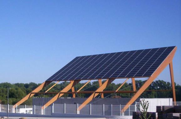
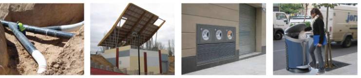
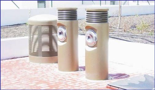
AGFA
Sector of Aranjuez - Madrid. Envac has installed a system of pneumatic collection
in this town council declared Heritage Site by Unesco. The installation of AGFA
Sector in Aranjuez collect the waste of 1.700 houses and the terminal has these
solar paneles that cuold produce 50 Kwh
INDEX
Content
2. Description of Envac Systems
5. Description of the proposed solution
6.3. Specifications to fulfill in the Building
7.1. Estimated budget removing 2 fractions
7.2. Estimated budget removing 3 fractions
1.
Object
The Fernbank
Community study area is proposed to encompass approximately 650 hectares of
land between the established communities of Stittsville, Kanata West and Kanata
South, and extending south from Hazeldean Road to Fernbank Road.
 The recommended Fernbank Community Design Plan
reflects an urban community containing a population of approximately 28,027 to
31,351 residents, and approximately 9,718 to 10,977 dwelling units and 2,497 to
2,623 jobs.
The recommended Fernbank Community Design Plan
reflects an urban community containing a population of approximately 28,027 to
31,351 residents, and approximately 9,718 to 10,977 dwelling units and 2,497 to
2,623 jobs.
The objetive of the
document is the carry out of a preliminary study for the running of an Envac´s
pneumatic waste collection for Fernbank.
The study is made from
the economic and technical point of view.
 The
information used for the study is enough for a rough estimation, but for
further analisys would be needed Cad drawings and the number of dwellings per
plot.
The
information used for the study is enough for a rough estimation, but for
further analisys would be needed Cad drawings and the number of dwellings per
plot.
2.
Description of
Envac Systems
The Envac system is
totally watertight, eliminating therefore the bad smells and dirty that
normally is produced inside the refuse room and in the containers in the
street. The waste is introduced through floodgates located outside or inside
the buildings. When the waste is thrown in the inlets nobody will get in manual
or visual touch with it. The classification of each fraction is made in origin,
using a specific inlet for each fraction.
The Envac pneumatic waste
collection systems are based on a network of pipes through which a powerful
airflow is in charge to transfer the waste to final point, where they are
stored in containers. The inlet doors to deposit in the system the waste can be
installed in all the plants of the buildings, in locations that are considered
more interesting for the operation of them.
When the exhausters
installed in the Collect station, are put into operation, and them create in
the system an airflow that allows the transport of the waste to the Collect
Station. Each valve of temporary storage is emptied in few seconds.
The system allows the
selective collection of different fractions of waste. All types of remainders
can be transported by the system, except the glass that cannot be collected as
separated fraction because it is a very erosive material and therefore it would
reduce the life of the installation.
By means of the system of
pneumatic collection, the waste is transported, by aspiration within
underground pipes, from its place of origin to a collect station, where they
are introduced in big containers
The pneumatic waste collections are made up of three
different parts:
þ
Inlet points
þ
Pipe network
þ
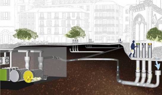 Collect station
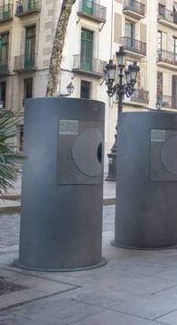 Inlet Points
The inlet points can be
located inside the buildings or like inletboxes in the public roadway,
depending on if it is a new urbanization area or consolidated area.
The waste is introduced
through the inlet doors. The vertical chutes connect these inlet doors with the
waste valves, located in the basement of the buildings.
The valves normally are
closed and they are opened during 7 to 10 seconds during the cycle of
collection, that usually is repeats two or three times to the day. When the
valves are closed, the waste that falls by gravity through the vertical chutes
is stopped by the valve element of closing until the operation of collection
starts.
When the valve is opened,
the waste fraction falls by gravity / aspiration in the airflow of the
transportation pipe. In the end of each branch of pipe an air valve is
installed, the air valve regulates the air entrance to the system, with the
intention of create the air current.
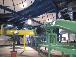
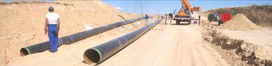
The pipe network is made up by steel pipe of
diameter 500 mm and variable thickness. The correct determination of this
thickness has a great importance, due to the considerable erosion that high
speed of the waste, that circulate through the pipe, causes. Anyway, this high
speed does that the bends and the branches of the network must have certain
geometric conditions.
In big networks, Sectioning Valves, that isolate
the main braches of the pipe network, are installed.
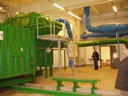
Collect Station
In the collect station all the equipments are installed for make the aspiration of the waste, separate it of the air and compact it inside the containers. From the collect station, the signal and the necessary compressed air to drive all the elements that make up the system are provided.
 In the collect
station, the waste is separated of the air of transport in the waste separator
that is made up of a cyclon and rotative screen.
In the collect
station, the waste is separated of the air of transport in the waste separator
that is made up of a cyclon and rotative screen.
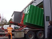
Once the waste and the air are separated, fall
into compactor and that introduces and compact them inside big containers. An
automatic transporter is in charge to replace the full containers by other
emptinesses.
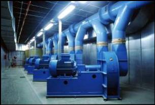
The aspiration that makes the pneumatic
transport of the waste possible from the different points to collect station is
made by the serial connection of the exhausters. Later, the sucked air pass
through a synthetic filter where the particles of dust are eliminated and
before be expelled to the outside, the air pass through a silencer
A compressor with auxiliary equipments provides
compressed air that activates all the valves located throughout the network
The collection process, that works
automatically, is controlled and supervised by the control system with
computer. By means of a modem, this equipment can be connected to another
control system at a distance.
The only operation that requires labour is the truck
that transports the full containers to the disposal place. Once the containers
are empty, they are located again in the terminal.
3.
Types of
Installations
The modern pneumatic
waste collection systems with selective collection, can be installed in residential
areas that vary between 200 and 8.000 dwellings.
In big areas, from 600 to
10.000 dwellings, are used systems with pipes of transport with a diameter of
400 mm or 500 mm. In this type of installations, named “Big Systems of
Pneumatic waste Collection with Selective Collection”, the different fractions
of waste are transported by an only one network without previous treatments or
trituration.
In small areas, from 200
to 600 dwellings, are used systems where the diameter of the pipe of transport
is small, 400 mm. In this type of systems named “Small Systems of Pneumatic
waste Collection with Selective Collection", the different fractions of
waste are transported by an only one network with previous treatments or
trituration.
Three types of systems of
collect stations exist, offering three alternatives by combination of
equipments:
F System
The main characteristic
is the absence in the collect station of compactors of waste and cyclons, due
to this all the equipments are located in a single plant. It does not need any
device of movement of containers. It is conceived to offer service to a maximum
number of houses of 1,200 with selective collection of 1, 2 or 3 fractions.
G System
This collect Station is
conceived to offer service to a maximum number of equivalent dwellings of
3.500. The difference of G system regarding F system is that the separation of
the air and the waste are made in a hopper that directs the waste to the
compactors. All the installation is developed in a simple plant with an
approximated vertical clearance of 5 meters.
C System
Collect Station with
waste compactors and cyclons, these cyclons will be located in the upper floor.
The movement of containers can be made with bridge crane or with a conveyor of
containers in the case of collect stations with the two plants in surface.
This power station is
conceived to offer service to 8,000 equivalent dwellings, with possibility of
selective collection of 1, 2 or 3 fractions. If the number of dwellings is
exceeded, it will be necessary to require the equipments of two collect
stations, being able to locate in two separate collect stations or in shared
building.
4.
System Advantages
The environmental
technical justification of the implantation of the system comes with the
following benefits that the action entails.
Sustainability
The automatic waste
collection represents a very clear differential note respect to the traditional
collection of waste. It contributes perfectly to one better quality of life of
the citizens and is integrated in the SUSTAINABLE
CITY concept.
Elimination of negative effects
It eliminates the
negative effects of the traditional systems of waste collection: noises, bad
smells, problems of traffic, etc.
A profitable investment
ENVAC is an extremely
effective system. It allows to a better use of the space and a more rational
waste handling, as well to reduce substantially the operation cost.
Better environment
Waste is transported
underground in the ENVAC hermetic system; thanks to this we increase the
aesthetic aspect of the area and its hygiene. We avoid foul smelling problems
and all the other aspects related with the waste collection rooms or containers
on the streets.
Service to the user
It provides to the user a
service where the system arrives until its house or a close point of it.
Flexibility
and life of the installation
It is flexible to the
changes, lasting in time, reliable and adaptable to the selective collection of
different fractions.
Separation of the fractions
It makes easy the
separation in origin of the waste fractions, contributing to the recycled.
Available 24 hour per days
The discharge points are
located close to the user, inside the buildings or in the street, and they are
emptied automatically whenever needed. The ENVAC system is available 24 hours
per day, 365 days per year, thanks to its reliability.
More free space
We free rentable space
both public and inside buildings, which can be used for more creative and
efficient aims, as green areas or pedestrian areas.
It avoids contact with the waste
Once the user introduces
the waste in the system, nobody already returns to have manual or visual
contact with it.
Reduction of the heavy traffic
Using pipelines to
transport waste to the collection station, we reduce the heavy truck’s traffic.
Reducing air pollution and the noise level and we increase the safety and the
comfort of the area inhabitants.
Better
health and work environment
Using an ENVAC system to
collect waste sensibly increases health and quality of the job. Nobody enters
in manual or visual contact with the refusals.
Therefore, the viability
of the implantation of the system, from all the points of view, is clear,
although it is difficult and complex to carry out with detail an evaluation
cost/benefit, due to some of the benefits are hardly to quantify.
.
5.
Description of
the proposed solution
5.1.
Scope
This study tries to give
a solution to the collection of the urban waste generated in the new
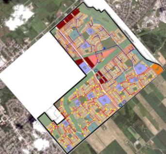
development areas located in Fernbank (Ottawa).
 The system of pneumatic waste collection demands the installation of two
collection stations. In this feasibility study we propose a place to locate
these terminals.
The system of pneumatic waste collection demands the installation of two
collection stations. In this feasibility study we propose a place to locate
these terminals.
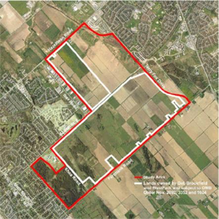
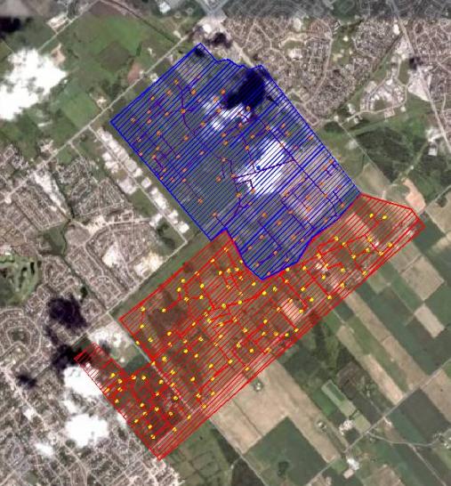
The terminal 1 will be
removing an area of 335 HA (in red color in the picture) and the terminal 2
will be removing an area of 315 HA (in blue color in the picture).
![]()

5.2.
Departure
data
Departure data used has
been the tables “Dwelling Unit Projections” and “Population Projections” of the
document “Fernbank Community Design Plan”.
6.
Design Plan.
SYSTEM DESIGN TO COLLECT FERNBANK - A NEW DEVELOPMENT AREA IN OTTAWA.
 According with the info received, we have designed two systems, this
mean to build two terminals, because total area has 12.587 equivallent dwelling
(residential and commercial use and services sector)
According with the info received, we have designed two systems, this
mean to build two terminals, because total area has 12.587 equivallent dwelling
(residential and commercial use and services sector)
The systems that will give
service to collect 3 fractions (recyclables, organic and rest) of the complete
development.
We propose a economical
option to collect only 2 fractions.
The total pipe network
will have around 36.000 meters of pipe with a diameter of 500 mm.
The location of the
inlets will be in the street, with the exception of some inlet points that will
be inside the building, depending of type residential area.
One of the preliminary
conditions in the layout of the pipe network is that it must be straightest
possible trying to reduce costs of installation, energy consumption and erosion
in the pipe.
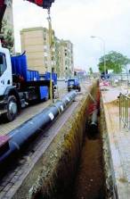
For the execution of the
pipe networks it will be necessary execute digging workings, construction of
lodging wells of the inspection openings, construction of the chambers for the
air entrance to give service to the installed inlet boxes in the street, and
the construction of chambers for the sectioning valves.
 The depth of the pipe network could be variable due to the pneumatic
waste collection system allows the reverse-slope collection. The maximum slope
admitted is approximately 20%. In any case and to avoid deformations by traffic
loads the bottom of the pipe would not have to be to less than one meter of the
ground level without protection of a concrete slab. In any case, like in the
plant drawings, the profile of the network must be the flattest possible,
within the possibilities, due to this will suppose a smaller power consumption
and a smaller erosion of the materials.
The depth of the pipe network could be variable due to the pneumatic
waste collection system allows the reverse-slope collection. The maximum slope
admitted is approximately 20%. In any case and to avoid deformations by traffic
loads the bottom of the pipe would not have to be to less than one meter of the
ground level without protection of a concrete slab. In any case, like in the
plant drawings, the profile of the network must be the flattest possible,
within the possibilities, due to this will suppose a smaller power consumption
and a smaller erosion of the materials.
Nevertheless in those
points in which the inlet boxes are located on the streets the ditch level will
have to be of 2.75 meters of depth.
The chambers of the
sectioning as well as the chambers for the location of the air valves will have
to be executed to guarantee the water tightness of them.
The well of the inspection
openings will be located to a maximum distance among them of 80 meters. Next to
the inlet boxes groups an inspection opening will always be located.
According to the
requesting to which the pipes are exposed, the materials to use will be the
next ones:
The straight pipe will be
of carbon steel, helicoidally welded with a machine type HELIXWELD with double
internal and external welded seam cordon by the procedure called “sumerged
arc”. The quality must be DIN St 37.2 or according with the Swedish norms SIS
1312 o ASTM A 105 grades B.
Also is permissible,
mainly in great thickness, straight pipe with a longitudinal welded, also with
double internal and external welded.
The thickness of the wall
can range from 5 to 22 mm depending the stretch of the installation. The
internal diameter of the pipe will always be 498 mm.
Bends with a spirally or
longitudinally welded, with quality St 52.3, or according with the Swedish
norms SIS 2101, o ASTM A 155 grade CMSH 70/1:
þ
Internal diameter
.................. 498 mm
þ
Thickness of the
wall.................. De 8 a 18 mm
þ
Radius of
continue curvature ...1.800 mm
þ
Angle of
curvature ..............From 10° to 90°
þ
Treatment of the
surface .......Polyethylene 3 layers coating or similar.
The bends will be of
continue circular curvature of carbon steel, made from helicoidally welded
pipes according with the chapter of straight pipes. In any case mitred bends
will be accepted.
The bends of this
material will have a minimum thickness of 8 mm and a maximum thickness of 18
mm.
The radius of curvature, measured in axis, will not be less to 1,800 mm
for this material.
Ni-Hard metal Bends
The Nihard material of
high hardness is adapted for those points where steel ST 52,3 cannot assure a
life expectancy superior to 30 years.
The minimum radius of
curvature is 1500 mm with thicknesses from 18 mm.
The join of the Nihard
material will be realised by the special connection, but never by welded.
Prefabricated conections
of straight pipes. The lenght of the main part is 2,5 m and the lenght of the
part of the conection is 1,5 m. The angle between the main part and the
connection part is of 30º.
þ
Internal Diámeter
...................... 498 mm
þ
Thickness of wall
......................From 5 to 22 mm
þ
Treatment of the
surface ...........According straight pipes
They are prefabricated
pieces of straight pipe in agreement with their specifications, made up of a
main stretch of 2,5 m and a connection of 1,5 m.
The angle of the
connection must be 30º.
Comunication
Network
The mechanical elements of
the system will have to be activated by automatic-pneumatic mechanisms.
To do it, it must have a
parallel network signal cable and pneumatic tube that it will run in conduits
of minimum section of 60 mm. Each pair of signal cable and pneumatic tube will
run through one of these conduits. At less an empty conduit will always exist
prepared as guide for futures cables or possible extensions.
Taking care of these
criteria the characteristics of the communication installation to implant will
be:
|
Protection
Conduit |
Description |
Protection Pipe |
|
|
Material |
Polyethylene |
|
|
Diameter |
63 mm |
|
|
|
|
|
Electric
Cable |
Description |
Reinforced Cable for the
transmission of the digitalized signal. Plaited and screened cable for
special protection against external and internal interferences. |
|
|
Pairs |
2x4+2x2x0,5mm2. |
|
|
|
|
|
Pipe for the
compressed air |
Description |
Pipe for compressed air in
Polyethylene for 10 atm of pressure. |
|
|
|
Æ 16 mm / 11 mm |
|
|
|
|
|
Boxes of
conection in wells and chambers |
Weidmuller |
|
|
|
IP67 |
|
6.1.
External
inlet points
To collect 3 fractions,
there will be a total of 480 inlets outdoors, (240 inlets in each area)
We have offered in that
case the installation of those inlets in a T connection that avoid the building
of a chamber.
We have offer also of
inlet called FS. (Domestic and commercial use)
The waste is temporary stored inside the inlet, being hold through a low
discharge valve fixed to that inlet. When this valve receives the open signal
instruction from the control centre, the waste is removed and vacuum to the
collection station.
The inlet has a single disposal door where it can be deposited domestic
or commercial waste respectively. It has been defined three types of inlet
according to their use: Domestic or Commercial.
6.2.
The Collection Station
The collection
station proposed is a C system designed to collect 3 fractions. As we said, to collect total area it’s need to install two
terminals.
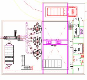
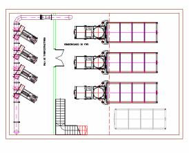
 The dimensions of the building are 21m x 28m.
The installation is developed in two plants. The height of the building will be
9.5 meters. Besides this is the height that is necessary for the accomplishment
of the maneuver of load and unloading of the truck.
The dimensions of the building are 21m x 28m.
The installation is developed in two plants. The height of the building will be
9.5 meters. Besides this is the height that is necessary for the accomplishment
of the maneuver of load and unloading of the truck.
The building counts on
the following rooms:
þ
 Room of containers
þ
Control room
þ
Fans Room
As well the existence of
a small warehouse and a electrical cabinets rooom is recommendable that would
release of space the control room.
A transformer cabinet
room if it will be integrated in the terminal.
 Control System.
Operated by means of a
Scada system, that allows an intelligent management of the installation. The
data base of the Scada system allows as well to extract historical data of
energy consumption, running hours, alarms, etc, so that it allows a programming
of preventive maintenance oriented to objectives
Telecontrol system.
The system allows to make
a pursuit and management of the installation from Internet. This favors the
control of the installation by the customer, that could have a system of
supervision in the offices with information of the operation in real time, and
the management, update and operation of the system by means of a remote server.
Our equipment of Operation and maintenance can in this way make managements on
the installation (modifications in the programming, or management of alarms)
from any part of the world.
Smell filtration
It is fundamental to
guarantee a purification of the air of transportation, that otherwise would
cause great annoyances to the houses near the collection station.
 In order to obtain the maximum effectiveness in air purification, Envac
has developed a system of filters prefabricated in factory, that they guarantee
the watertightness, as well as the maximum output of the filters. This room of
filters will be equipped with two stages with filtrate of particles and other
two stages with filters with active carbon, guaranteeing a high time of contact
of the air with the carbon, element that neutralizes the smell coming from the
waste transportation The efficiency of the purification of the air from exit to
the atmosphere has to be like minimum of 95%.
In order to obtain the maximum effectiveness in air purification, Envac
has developed a system of filters prefabricated in factory, that they guarantee
the watertightness, as well as the maximum output of the filters. This room of
filters will be equipped with two stages with filtrate of particles and other
two stages with filters with active carbon, guaranteeing a high time of contact
of the air with the carbon, element that neutralizes the smell coming from the
waste transportation The efficiency of the purification of the air from exit to
the atmosphere has to be like minimum of 95%.
Other methods of the
filtration exist but they have been demonstrated ineffective for the systems of
pneumatic collection. In the case of the biofilters, the variation of the
temperature of the air of transportation due to the heating when happening
through the fans, as well as the fact that the air flow that cross the
biofilter is discontinuous since the power station only operates during certain
hours within the day, causes that the death of the bacteria that facilitate the
air filtration.
 Reserve exhauster.
The power necessity to
guarantee the collection of all the waste production is covered with the
installation of 2 fans of 90 Kw. However, the waste collection must be
guaranteed 24 hours to the day and 365 days to the year. For that reason, Envac
supplies the installation of one reserve fan that will guarantee the
availability of necessary power in spite of any problem with one of the others
fans. In addition the availability takes advantage of this extra fan to
alternate the running hours of the extractors and thus to guarantee a greater
life spam of the equipment, and a reduction in the maintenance cost.
6.3.
Specifications
to fulfill in the Building
Besides of geometrical
conditions, the building should be design with the observance of the next
requeritments.
Acoustic
Isolation
Acoustic isolation of the
several rooms according with the local regulations. The values of the acoustic
emissions in the several stays of the terminal, measured from a meter of the
equipment are the following ones:
þ
Fans Room 99
dB(A)
þ
Compactors 75
dB(A).
þ
Filter Room
76 dB(A).
þ
Diverter valve 79
dB(A).
Ventilation and air
conditioning
Minimun of 6 air
renovation per hour inside compactors room.
In the fans room requires
air conditioning due to the maximum temperature shouldn’t be over 35ºC.
AC in
control room
Power
Supply
Power supply from a
transformer cabinet, It could be integrated inside the building.
Collect Station of Shouthern
Hills
7.
Budget
7.1.
Estimated
budget for 2 fractions
|
PIPE NETWORK T1 |
8.970.000,00 |
|
PIPE NETWORK T2 |
7.728.000,00 |
|
OUTDOOR
INLET POINTS T1 |
5.576.002,90 |
|
OUTDOOR
INLET POINTS T2 |
5.698.292,10 |
|
TERMINAL 1 (T1) |
1.573.708,31 |
|
TERMINAL 2 (T2) |
1.573.708,31 |
|
TOTAL |
31.119.711,62 |
·
Fractions:
recyclables and rest.
·
36.300 pipe
meters.
·
230 outdoor inlet
points model FS.
·
2 C Terminal (T1
+ T2).
·
Price in €
7.2.
Estimated
budget for 3 fractions
|
PIPE NETWORK T1 |
8.970.000,00 |
|
PIPE NETWORK T2 |
7.728.000,00 |
|
OUTDOOR
INLET POINTS T1 |
5.809.787,60 |
|
OUTDOOR
INLET POINTS T2 |
5.932.076,80 |
|
TERMINAL 1 (T1) |
1.912.366,10 |
|
TERMINAL 2 (T2) |
1.912.366,10 |
|
TOTAL |
32.264.596,60 |
·
Fractions:
organic, recyclables and rest.
·
36.300 pipe
meters.
·
240 outdoor inlet
points model FS.
·
2 C Terminal (T1
+ T2).
·
Price in €
Note about the budgets:
Those prices are estimated. More detailed project should be necessary.
The scope of the price is supply, assembly, and commissioning.
Prices in EUROS
Taxes not included
Civil works are not included in this estimations.
This prices consider that our materials are excluded of custom tariff.
Changes on tariff could affect to the final prices.